Background#
Vacuum bagging is often used as a method to clamp and consolidate composite laminates. It is particularly useful for fibre sandwich composite where the vacuum bag provides a force that bends and holds the foam core to the required shape as the resin cures. A good guide to the technique is give in the West Systems document Vacuum Bagging Techniques
A vacuum pump is used to create the required vacuum. Running the vacuum pump continually may create too strong a vacuum which may crush the core or cause resin starved components. The data-sheet provided with the resin I used recommended a maximum vacuum of 80% (i.e. 80 kPa below atmosphere). In order to control the vacuum I built an electronic controller that is designed to switch off the pump once a certain low pressure is reached. When the pressure rises back up to a certain level the controller then switches the pump back on. There are two independent system described in the following.
System 1#
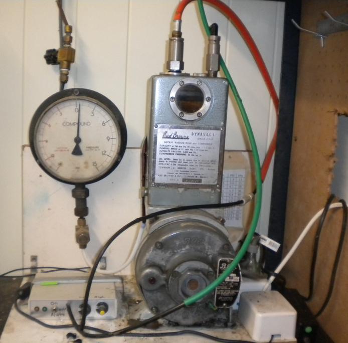
This system uses a Rud Browne, DynaVac 1 single stage rotary vane vacuum pump, Figure 1. These were an Australian made pump but it seems the company is no longer in business. The name plate gives a capacity at 760 mmHg of 30 $\ell$/min. a pumping speed at 0.1 mmHg of 0.3 $\ell$/s and an ultimate vacuum of 0.005 mmHg (i.e. 0.6 Pa or 99.999 % vacuum).
The circuit diagram for the vacuum controller is shown in Figure 3. The main components are a differential pressure transducer, a difference amplifier, a micro-processor, and a transistor driving a relay switch.
The pressure transducer is a strain gauge device that outputs a voltage difference, $\Delta V=V_2-V_1$, which is proportional to the applied pressure (or vacuum). The pressure transducer is a differential unit, that is it measures the pressure difference between port ‘A’ (high pressure) and port ‘B’ (low pressure). Port ‘A’ is left unconnected (i.e. vented to atmosphere) whereas port ‘B’ is connected to the vacuum line. This creates a positive pressure difference on the sensor as the vacuum draws down. The sensor has a maximum range of 15 PSI and at full scale gives an output of $\Delta V=250 mV.
The sensor output voltage is amplified using a differential amplifier (part no. INA103). The gain on this amplifier is set using resistor $R_G\approx 320\Omega$ and this gives an amplifier gain of $G=20$. The output of the amplifier is then in the range 0 to 5 V (full scale). This voltage is sampled by the Arduino on the pin labelled “analog in 1” (A1) on Figure 3.
The Arduino also samples two other reference voltages on “analog in 2” (A2) and “analog in 3” (A3). The microprocessor compares the sensor voltage A1 to the reference values A2 and A3. If A1<A2 the pump will turn on then when A1>A3 the pump turns off. The voltage A2 and A3 are adjusted by turning knobs on the controller front panel. Hence, the desired turn-on and turn-off vacuum pressure levels can be set. Importantly the difference between the values of A2 and A3 can be used to generate a hysteresis effect so the the pump does not “hunt” on-off/on-off.
The actual switching of the pump is initiated via the low current trigger signal sent out of the Arduino. When this signal is at 5 V the transistor (part no. BD681) switches on and current passes through the relay coil from the 12 V power supply, switching the mechanical relay and hence the compressor on.
Invariably there will be small leaks in the bag. The effect of these leaks on the vacuum level can be greatly reduced by placing a vacuum “reservoir” in the circuit, to achieve this I used a 9 kg gas bottle. With a well sealed bag and a vacuum reservoir the pump would switch on for about 1 min. each half hour or so.


System 2#
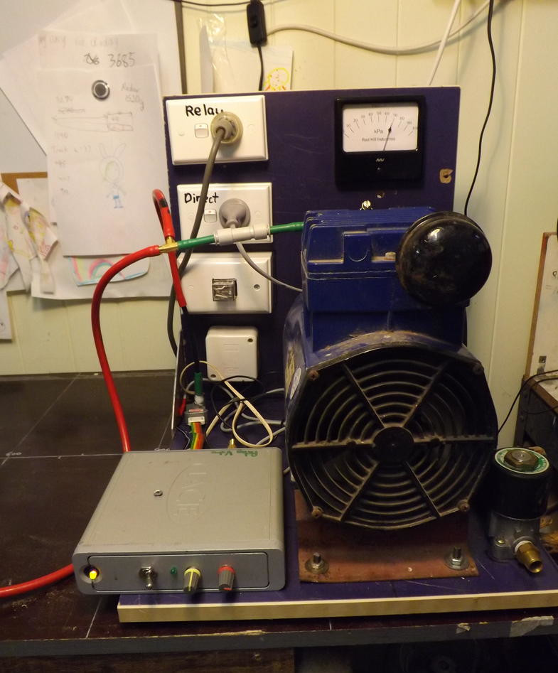
This system uses a Thomas Industries piston air compressor vacuum pump, model 707CH82. The name plate only gives the motor specifications 1.4 Amps at 230 Volts. A search of the internet did not return this actual model but it looks similar to the 607 and 617 series. These models have a pumping rate of 20 to 29 $\ell$/min. at atmospheric pressure (depending on actual model) and ultimate vacuum of 13 kPa (i.e. 88 kPa below atmosphere or 87% vacuum).
The principle of operation, of the controller, is very similar to the system 1 version. The difference are system 2 has a:
- Texas Instrument microprocessor.
- Pressure transducer that outputs an amplified analog voltage, proportional to the applied pressure.
- Solenoid driven “blow-off” valve to release the vacuum from the vacuum pump when the pump is idle.
The input to the vacuum pump is tee-pieced and the vacuum bag side is is always held at the vacuum pressure whereas the other side is momentary vented to atmosphere (via the blow-off valve) when the pump switches off. The vacuum bag side is connected to the pump via a non-return valve so that the vacuum on this side is not released when the blow-off valve opens. The reason for the blow-off valve is to ensure when the pump re-starts it does not have a pressure load initially on it. It was found that while the pump would restart if there was a load on it, it did hesitate under such circumstances and I was concerned it may cause the winding to burn out it the pump remained stalled. For version 1 the blow off valve was not necessary since the pump did not hold the vacuum when idle and hence only the non-return valve was require for version 1.